Using WSL in Windows
In this tutorial will show you how to develop your projects based on
Visual Studio Code+ESP-IDF Extension+Remote - WSLto implement all features of this extension in WSL.Install the following tools before starting the project:
Windows WSL (steps to install below).
Installing Ubuntu on Windows (WSL)
If you don’t have WSL installed run:
wsl --install
Update the WSL kernel with
wsl --update
Check the WSL available distributions list with the
Powershellcommand prompt, as below:
wsl -l -o
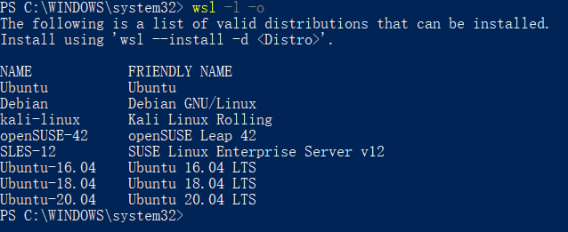
So to install a ubuntu distribution in WSL on Windows, please type in the following command:
wsl --install --distribution Ubuntu
usbipd-win in WSL
To access the
USB,serialandJTAGdevices which are from the local Windows,usbipd-winmust be installed, else it is impossible to download,monitor and debug on IDF docker image side. the way to install it, it is also same as Windows applications, so it will not be described in detail here.You still need to do a bit configurations after installing the four tools above:
Check Ubuntu on Windows (WSL)
Check the current WSL version is 2
wsl -l -v
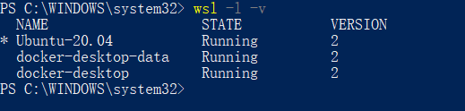
Please upgrade to version 2, if not
wsl --set-version Ubuntu 2
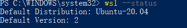
Set the Ubuntu distribution as default:
wsl -s Ubuntu
At last, to check if the commands have taken effect with
wsl --statuscommand.
Adding the Required Linux Packages in WSL
Install ESP-IDF requirements for Linux.
sudo apt-get install git wget flex bison gperf python3-pip python3-venv python3-setuptools cmake ninja-build ccache libffi-dev libssl-dev dfu-util
Install usbipd in Powershell command prompt:
winget install usbipd
Now configure the USB serial device to be able to connect to the WSL with
usbipd:Open PowerShell command prompt with administrator rights and then type in the command
usbipd list
for a list of USB serial devices.
To access the specified device from Windows on WSL locally, the device must be bound with usbipd. Open PowerShell command prompt with administrator rights and then type in the command:
usbipd bind --busid <BUSID>
Note
this command needs to be used only one time,unless the computer has restarted. 1-1 is the device’s bus id <BUSID> I would like to bind.
After binding, please attach the specified device to WSL with this command in the Powershell command prompt.
usbipd attach --wsl --busid <BUSID>
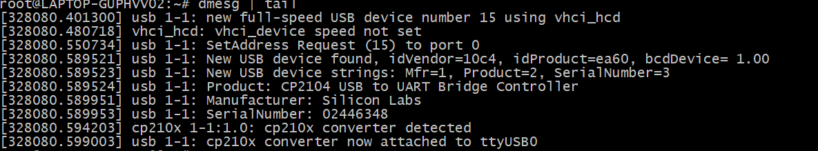
At last, let us check if it works well on both side and type this command on WSL side.
dmesg | tail
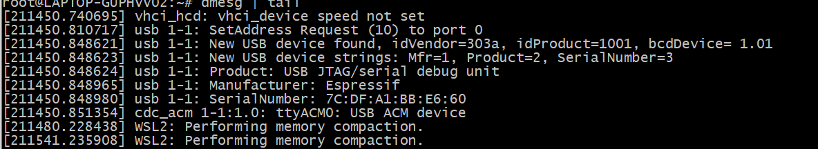
As we can see above, 1-1 device has been attached to
ttyACM0, that means WSL can access the 1-1 USB device now.
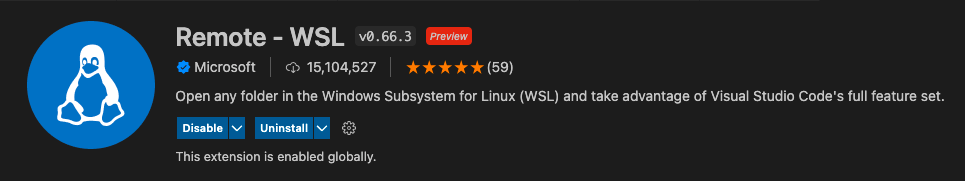
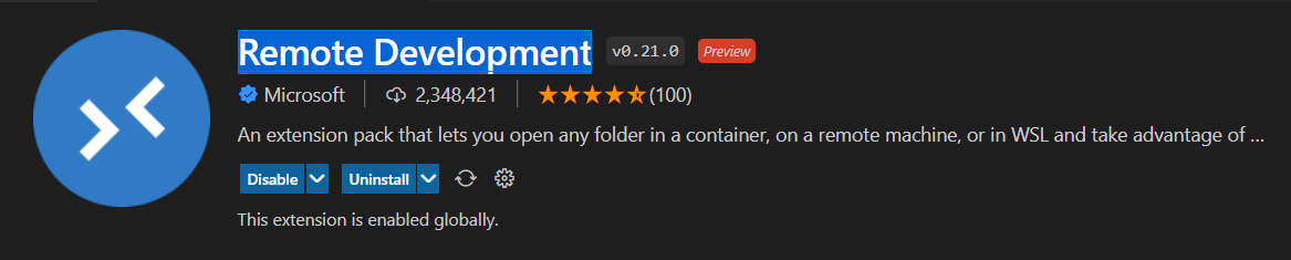
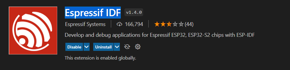
Install Remote WSL extension in Visual Studio Code
Install the Remote - WSL, Remote Development and ESP-IDF extensions, as below:
Open Project in WSL
Start your development by clicking the
><green button at the left bottom of Visual Studio Code and select Open Folder in WSL to start configuring the WSL and open theBlinkexample project.Configure the ESP-IDF extension inside the WSL as described in the Install ESP-IDF and Tools documentation.
Note
Running the setup from WSL could override the Windows host machine configuration settings since it is using the User Settings by default. Consider saving settings to a workspace or workspace folder.
At this moment, you can start to use the
Blinkexample project for building, flashing, monitoring, debugging, etc.
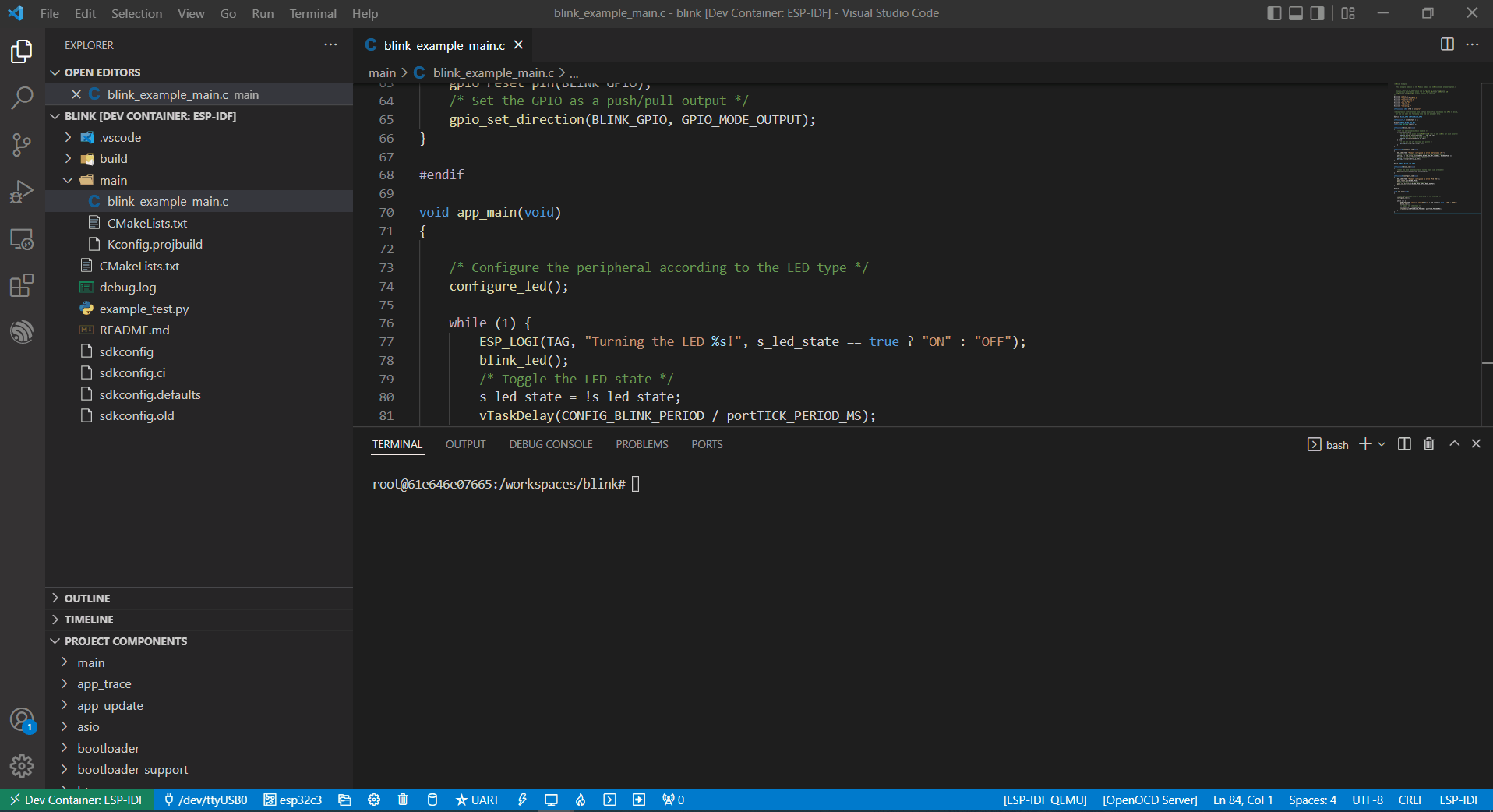
Building the Project
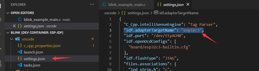
Here taking the esp32-c3 as an example, users only need to change the target device from
esp32toesp32-c3, as below:
Next, start to build the example project, as below:
Flashing to your Device
After building, we can use the following ways to download the firmware.
External USB-Serial
Based on the description above, users can follow the usbipd instructions section mentioned. here
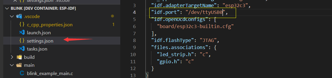
Silicon Labs CP210x USB to UART Bridgeis taken as an example, it has been attached to docker image:
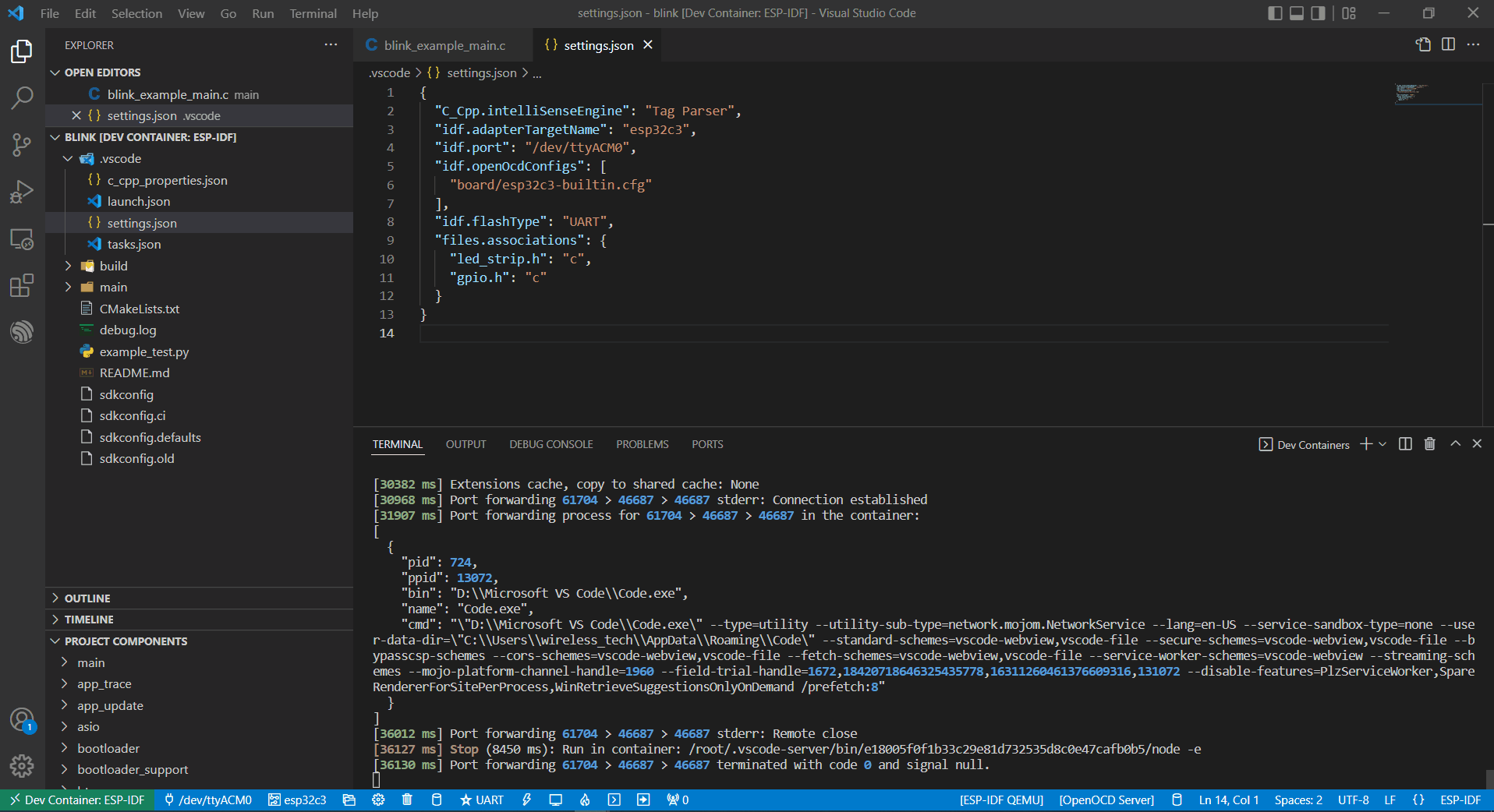
As you can see, this device has attached to
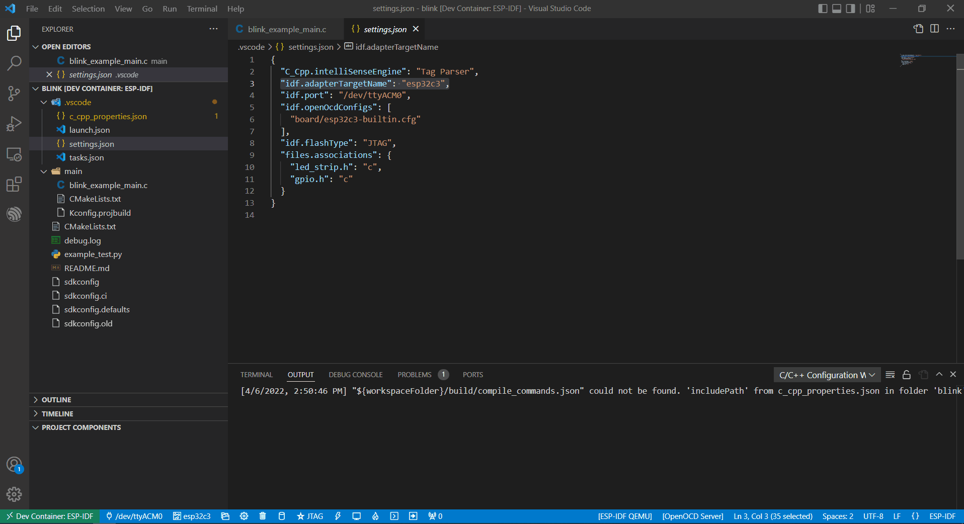
ttyUSB0, soidf.portalso need to change accordingly.
But, the container doesn’t know the configuration has changed yet at this moment.
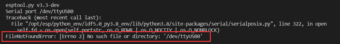
So users need to reopen the container, that is Reopen Folder Locally and then the new configuration wil be reloaded as well.
At last, click the
Flashbutton and start to download the firmware.
Internal USB-serial
Just as the External USB-Serial, the only difference is the number attached. where the external usb-serial is ttyUSBx, while the internal usb-serial is ttyACMx.
USB-JTAG
Same as External USB-Serial and Internal USB-serial, but it needs to configure the following extra parameters:
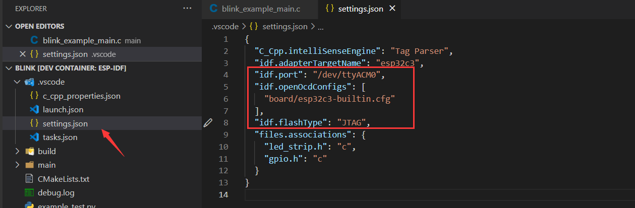
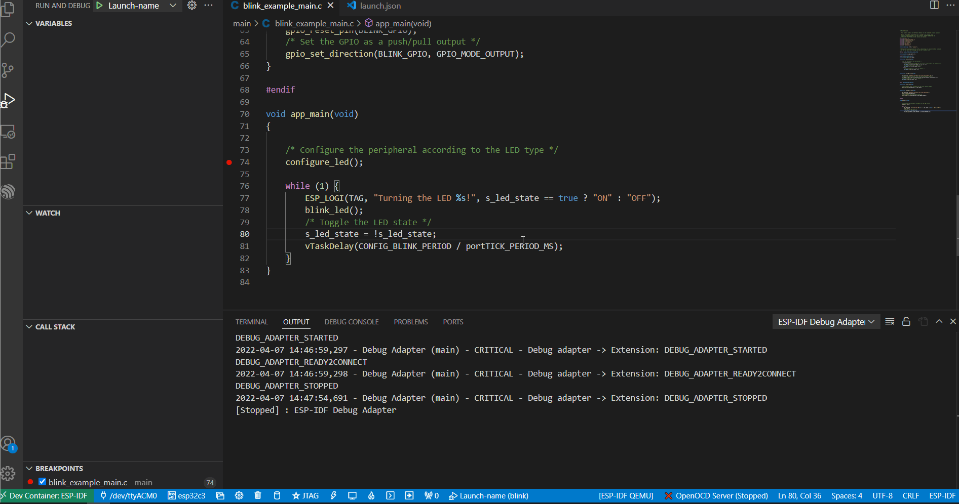
the interface is the same as Internal USB-serial, that is ttyACMx:

Additional steps for debugging
Make sure to copy the OpenOCD udev rules files into the /etc/udev/rules.d directory before running OpenOCD and starting a debug session.
Precautions
If you want to debug on Windows, you need to unplug the USB cable and re-plug in it again, otherwise the corresponding USB port cannot be found in the Windows device manager.
Docker Desktop For Windows needs to be opened and cannot be closed during container development.